GOES Satellite Hunt (Part 1 – Antenna System)
 Written by
Lucas Teske
Written by
Lucas Teske
on
So few people know that I started a crusade against GOES 13 Satellite. My idea was to capture the GOES 13 signal (that’s reachable in São Paulo) with a good SNR (enough to decode) and them make all the toolkit to demodulate, decode and output the images and other data they send. I wanted a high-res image, and the L-Band transmissions usually provide that (GOES for example is 1km/px with whole earth sphere in frame. A 10000 x 10000 pixels image)
So I choose GOES over other Weather Satellites mainly because GOES is a Geostationary Satellite. That means its position never change. That was needed for me, because L Band usually needs a relatively big dish to capture the signal, and if the satellite is moving, the antenna needs to track it. That means: Alt-Az tracker (or something else) that will be most likely more expensive than the whole capture system (at least in Brazil). Since GOES does not move, I could just point my dish and forget about it. It would always capture the signal.
So first things first. What dish should I get?
I found some people in twitter ( More specific @USASatcom and @uhf_satcom and just for historic reasons: https://twitter.com/lucasteske/status/766484223431770112 ) that did Satellite Receiving and more specifically USASatcom also did GOES receiving. And from time to time posted pictures like this:
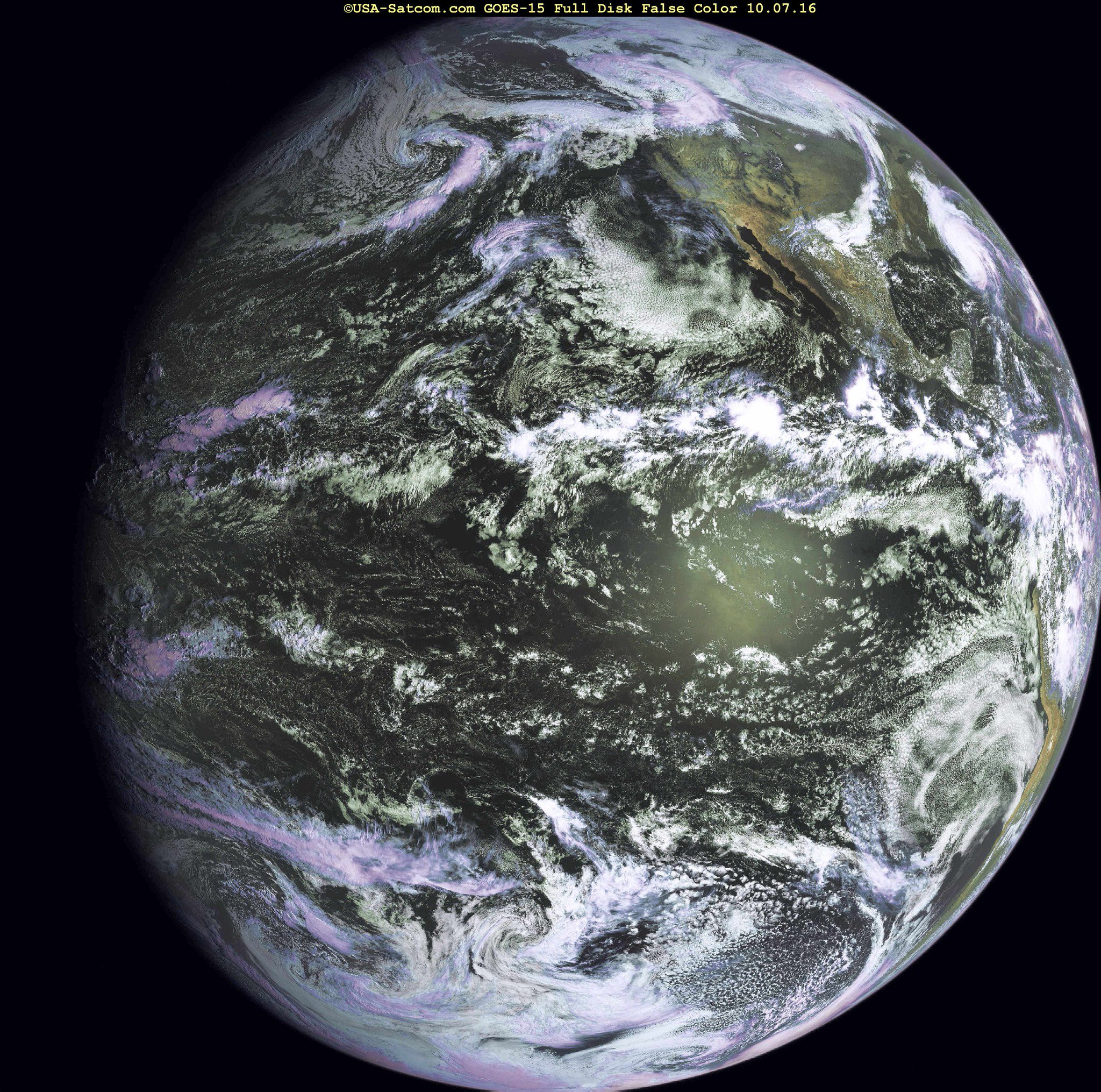
“It’s been a while so I thought i would post a nice full disk false color image from GOES-15 – just before mid-day.”
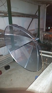
And then I found the IRC Channel called #hearsat in server StarChat ( irc.starchat.net ). So a lot of people actually helped me by giving me the information I need to take a decision over which dish antenna should I buy. They were suggesting a 1.2m offset dish (same time of the Sky, Claro, and some other TV dishes, but bigger) for receiving GOES. Sadly I couldn’t find a offset dish bigger than 90 cm here. So someone suggested that I need at least 1.5m prime focus (the “old” type of TV dishes) that should have equivalent surface area than a 1.2m offset dish. So I went to Santa Efigenia Street (people from São Paulo will recognize) and went to Sat Imagem Store. Since my father and I was already friends with a seller, I asked what dishes they had to sell and said that I want something around 1.5m. He said that he has a 1.9m dish to sell.
So I bought the dish, costed about R$200 (that’s about US$60) and also some cables and adapters. So since I was very excited to get things working, I asked my father’s help to assemble the antenna. I arrived home about 5 PM so it was very late to assemble the antenna. So I let it for the day after.
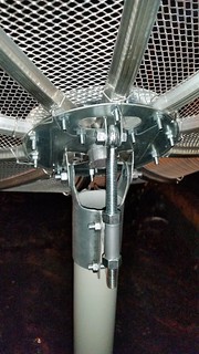
Assemble Process
So the assemble process was sort of straightforward. It was not easy to do, but even without a manual (that did not came) you should be able to figure out what piece goes where. We were in 4 persons, we started just after lunch (about 1PM) and took us about 6 – 7 hours to get it assembled. LOL
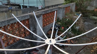
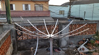
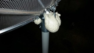
I also decided to inject Polyurethane Foam into the dish tube, so when it rains it doesn’t get filled with water. The only tip I have is: Be careful, your dish can grow balls.
So the dish assemble is done. Now we need to worry about the feed.
Dish Feed (The actual receiver)
So I did several tries for like one month and half. The guys in #hearsat and me was struggling to find what was the reason that I couldn’t get the signal. I have all pictures of my failed feeds here: https://www.flickr.com/photos/energylabs/albums/72157675387388535. I will not detail each one of the assembles of these feeds because it didn’t work. So for historical reasons as well the reason why they didn’t work is because of the illumination angle of the Helical Coils. Usually the Helix Feeds have a very narrow beam width (and high gain), this causes to only some portion of the dish to be actually used by the feed. I only discovered that when I drawed my dish in FreeCad and did some auxiliary lines to show the angles. Then I noticed that something was REALLY wrong: Only like 60cm of my dish was actually illuminated, and from this 60cm only 40cm was actually visible by the dish (we need to discount the dead center). This is the drawing I did. So mybit from hearsat suggested me a Wave Guide Feed. For those that used to hack wireless systems, this is known as CanAntenna or Cantenna. Its very simple to do and I found this calculator to get things better:
http://www.changpuak.ch/electronics/cantenna.php
So the image (from the site) is this:
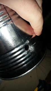
So if you check, the only thing that actually uses your target wavelength is the linear feed size (that uses lambda / 4). The other ones use lambdag that is the guide wavelength. The guide wavelength is calculated from the can diameter. So I just found a can here (Neston Can for those who want to buy in São Paulo) that has basically “square” size. The can has 12cm diameter and 12cm height. You can use basically any size of cans. Just a few things are important using that calculator:
- Keep your target frequency over TE11 and below TM01.
- The length of the can should be at least 0.75 * lambdag. Don’t worry if your can length is higher than that. Just try to keep close.
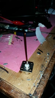
- The probe length (linear feed) counts from the base of the connector (where you put the screws.
More details about TE11 and TM01 are here: http://www.daenotes.com/electronics/microwave-radar/waveguide-modes-of-signal-propagation
In my case the parameters for the calculator was:
Freq. of operation [MHz] 1692
Can Diameter [mm] 120
Cut-Off Freq. for TE11 Mode [MHz] 1464.15
Cut-Off Freq. for TM01 Mode [MHz] 1912.38
Guide Wavelength [mm] (λg) 153.89
λg/4 [mm] 38.4725
0.75 * λg [mm] 115.4175
Wavelength λ/4 [mm] 44.325
These waveguides usually have really wide bandwidth ( mine can probably get anything from TE11 to TM01 modes ). So the sizes are not that critical. Even so, I would keep the probe (the linear feed) length close to few mm of the lambda / 4 of the target frequency.
The LNA and Filter
So in my failure setups I was having a REALLY huge noise from the GSM Band at 1800MHz. That was: even without any LNA I could get like 10dB of GSM signal. So mybit suggested me to use some filtering to wipe out this signal. So I bought some Lorch Filters (recommeded and sold by him) that has a center frequency of 1675MHz and 150MHz bandwidth (so from 1600 to 1750 MHz).

I also bought 3 LNA4ALL (one with connectors, two without) to use in this and other projects.
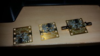
So if you want to build this as well, I strongly suggest to buy some LNA4ALL from Adam (its the manufacturer). They’re used by a lot of people around the world and they’re high end ones and relatively cheap (not for us in Brazil, but he sends in registered letter, so it never gets taxes and arrives in two or three weeks). More info: http://lna4all.blogspot.com/
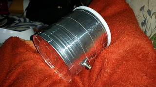
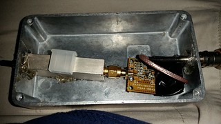
I also bought some aluminum boxes (in Santa Efigenia as well, but now in Multcomercial ) for putting these LNA and filters. I made some tests with the topology Feed -> LNA -> Filter, but it looked like the GSM Signals was overloading the LNA. So I decided for a non-optimal setup that is Feed -> Filter -> LNA that gave me what I want. So them I just tried to fit everything inside a box and here is the result:
Then I finished by gluing in the CanAntenna:
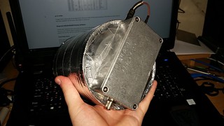
And that it!
Positioning the Antenna
So the last thing was to position the antenna. I actually did this before the step of the feed (since I tested several other feed types). But if you’re planning to build everything this should be the order that you do the stuff.
So in the past it would been tough to position an antenna, but today we have cellphones to help everything. One application I use in Android is Satellite AR. Another good one is Pointer Antena.
Satellite AR has a preset list of Satellites (including GOES), and Pointer Antena allows you to fill with the coordinates of the satellite. Both are good and enough for positioning, just be carefull that your compass needs to be calibrated.
Another solution would be use GPredict or Orbitron to get the Elevation (The inclination in relation to ground) and Azimuth (the bearing in relation to North) angles and position manually. I noticed that for my dish there is a working band of about 4 degrees of Azimuth and Elevation that the signal doesn’t change. I would recommend get your laptop / cellphone and hookup to the feed and check where you get the best signal.
Other two things that you need to care is related to the feed itself. Since we have a linear polarized feed, the rotation of the feed matters in relation to the satellite. This is less critical and I found that even 15 degrees rotation doesn’t change a lot the signal. Other thing is the focal point of the dish. You need to adjust the feed distance from the base of the dish to also get the best signal. Mine has the probe (the linear feed inside the can) in the focal point (so the can opening is far ahead). After all, you should get something like this (got with airspy, 10MHz bandwidth):


Continuing
So the next step is the whole decoding process. At the time of this writing I did not finish the whole demodulate -> decode process. For now I got the file output from GOES and need to decompress and convert the images, so I’m close. Once I finish, everything should be published in a Open Source License and I will create a new post here describing the whole process.
Special Thanks
Special Thanks to trango and mybit in #hearsat channel, for the help getting all of this to work.